
In continuous hot-dip galvanizing lines, heat dissipation within the furnace zone has long been a “silent killer.” Excessively high surface temperatures on the furnace shell not only accelerate the aging of electrical components and heighten the risk of downtime, but also render the area inaccessible to maintenance personnel—thereby severely compromising both production efficiency and safety.
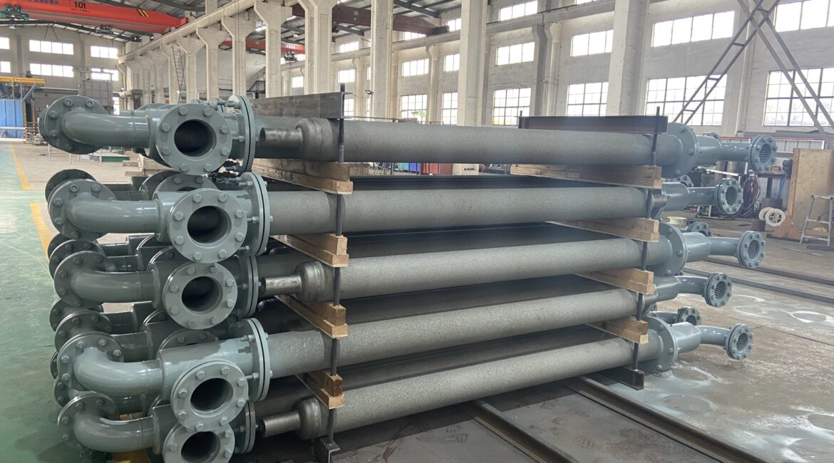
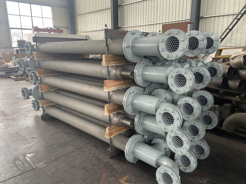
Thanks to their advantages—including safety, energy efficiency, and maintenance-free operation—air-cooled tubes have become the mainstream choice for cooling furnace bodies in galvanizing lines. However, during visits to numerous galvanizing plants, we discovered that many enterprises still fall into three common pitfalls when selecting or utilizing these tubes. By avoiding these traps, it is entirely possible to boost your heat dissipation efficiency by over 50%, while also significantly improving equipment longevity and operational stability.
Now, let’s break them down one by one.
Misconception #1: Focusing solely on airflow while neglecting air pressure and localized hotspot coverage
Typical Manifestations:
When making a purchase, the sole inquiry was, “What is the fan’s airflow volume?”—based on the assumption that greater airflow equates to faster cooling. However, following installation, it was discovered that while certain sections of the furnace body remained glowing red-hot, other areas were being overcooled by the airflow.
The Essence of the Problem:
Air volume (m³/h) represents the total air output capacity, but air pressure (Pa) determines whether the airflow can overcome duct resistance and reach high-temperature dead zones. The furnace body of a galvanizing line features a complex geometry, often presenting localized hot spots—such as within recesses, along weld seams, or near electrical interfaces. If the air pressure is insufficient, the airflow will take the path of least resistance within the main duct, resulting in virtually no airflow reaching the distal outlets.
The Correct Approach:
- When selecting equipment, pay simultaneous attention to both airflow volume and static pressure, and calculate the frictional resistance along the ductwork. For furnace systems involving long-distance runs or numerous bends, it is recommended to select a medium-to-high-pressure fan (≥ 800 Pa).
- Thermal imaging inspection is performed on the furnace body surface to identify the areas with the highest temperatures; specialized, localized air nozzles are then designed to target these specific hot spots.
- Adopts zone control: different airflow volumes and pressures are configured for different areas, thereby avoiding the waste associated with “uniform airflow.”
Avoiding this pitfall can often directly eliminate the 3 to 5 most critical hot spots, reducing the overall surface temperature differential from 80°C to within 20°C.
Misconception #2: Materials lack resistance to high-temperature flue gas corrosion, leading to rapid failure
Typical Manifestations:
The newly installed air-cooled tubes began shedding their fins and developing perforations in their walls in less than six months, causing their heat dissipation efficiency to plummet. Maintenance personnel complained, “We would have been better off not installing these air-cooled tubes at all.”
The Essence of the Problem:
The ambient air surrounding the furnace body of a galvanizing line contains corrosive constituents—such as zinc vapor, chlorides, and sulfides—with both temperature and corrosivity reaching particularly high levels near the exit of the annealing furnace and the zinc pot. Ordinary carbon steel ducts would corrode within a mere few weeks; even stainless steel, if the wrong grade is selected (e.g., 304), is susceptible to stress corrosion cracking in such high-temperature, high-chloride environments.
The Correct Approach:
- Substrate Selection: Core components exposed to hot air (such as nozzles and the inner walls of the main duct) must be constructed from at least 316L stainless steel or a higher grade of heat-resistant stainless steel (e.g., 253MA).
- Surface Treatment: Applying a high-temperature-resistant, anti-corrosive coating (such as an aluminum-silicon or ceramic coating) to the outer surface of the air duct effectively prevents the adhesion of zinc vapor.
- Structural Design: Avoid dust-accumulation dead zones; ensure smooth internal transitions within the air ducts wherever possible, and provide removable access ports to facilitate the periodic removal of corrosion products.
Misconception #3: Improper installation location leads to airflow short-circuiting
Typical Manifestations:
After the air-cooling pipes were installed, the fan was set to maximum speed; yet, the furnace body temperature still failed to drop. Reaching a hand in front of the air nozzle revealed a strong airflow, but thermal imaging showed that the heat was not being carried away at all.
The Essence of the Problem:
Airflow short-circuiting refers to a phenomenon where cold air, immediately after being discharged from the furnace surface, is directly drawn back into the fan inlet by an adjacent negative-pressure zone, thereby failing to facilitate effective heat exchange. Common causes include:
- The air inlet and outlet are too close to each other.
- The nozzle is positioned directly opposite an obstruction (such as a reinforcing rib or cable tray); the airflow rebounds and takes a detour before returning.
- The entire furnace body lacks a directional airflow pattern extending from the cold zone to the hot zone.
The Correct Approach:
- Prior to installation, use smoke tracing or CFD simulation to briefly verify the airflow path, ensuring that cool air enters from one side and hot air exits from the other side or the top.
- The air nozzle should be positioned at a reasonable distance of 50–150 mm from the furnace body surface, and ideally tilted at an angle of 15°–30° to guide the airflow along the furnace wall.
- Install a baffle or guide hood at the fan inlet to prevent the direct intake of freshly blown hot air.
- For large furnace bodies, independent air-cooling units can be installed in sections, with each unit featuring independent air intake and exhaust channels.
After correcting the short-circuiting issue, actual measurements indicate that heat dissipation efficiency can be improved by 40%–60%, while fan energy consumption actually decreases (as there is no longer a need to repeatedly recirculate hot air).
After Avoiding the Three Major Pitfalls, How Can You Achieve a 50% Increase in Heat Dissipation Efficiency?
The three misconceptions outlined above rarely occur in isolation. Many galvanizing lines simultaneously face a combination of issues: “sufficient airflow but insufficient air pressure,” “localized corrosion leading to nozzle clogging,” and “airflow short-circuiting.” Following targeted corrective measures, the retrofit data we have accumulated indicates the following:
- The maximum surface temperature of the furnace body decreased from 260–320°C to 60–90°C.
- The average temperature of the furnace shell decreases by 120–150°C.
- The rate of electrical failures caused by high temperatures has been reduced by over 70%.
- Overall heat dissipation efficiency (the amount of heat removed per unit of energy consumption) has generally increased by 45%–55%.
In other words, you don’t necessarily need to replace your entire equipment setup; simply avoiding these three pitfalls during the selection process will allow your air-cooled tubing to deliver double the performance.
Appendix: Quick Self-Check Checklist for Correct Air-Cooled Tube Selection
Prior to procurement or modification, please verify each item:
| Checklist Items | Compliance Standards |
| Airflow Calculation | Based on the furnace body’s surface area and temperature differential requirements, a preliminary estimate is made at 200–300 m³/(h·m²). |
| Wind Pressure Verification | After overcoming the resistance of the most unfavorable duct run, the static pressure at the air outlet shall be no less than 200 Pa. |
| Material Grade | For high-temperature corrosion zones, use 316L or a higher-grade material, featuring a corrosion-resistant surface coating. |
| Nozzle Design | Adjustable angle, dust-resistant structure, spacing ≤ 300 mm. |
| Airflow Distribution | Intake and exhaust airflow do not short-circuit; there is an independent heat exhaust channel. |
| Ease of Maintenance | Reserved cleaning port; fan motor protection rating ≥ IP55. |
Let professionals handle professional matters
Operating conditions for galvanizing lines vary widely—furnace dimensions, strip width, line speed, and ambient temperature all influence the optimal design of air-cooling tubes. Rather than relying on intuition to make a “best guess,” let our experienced team perform a precise, one-on-one calculation tailored to your specific needs. With 18 years of specialized expertise in air-cooling solutions for the metallurgical industry, your galvanizing line deserves an air-cooling system that is entirely free of pitfalls.